INTRODUCTION
This article provides summaries of operational limitations of a submarine, as well as basic mechanics about how a submarine operates at the surface, underwater, between the sea surface and bottom of the seabed, and how to float back to the surface. Below are the cycles showing how a submarine operates, as illustrated in Fig. 1.
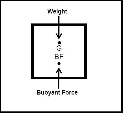
Fig. 1. Simple Buoyancy Calculations
To prove how this principle works, the following are the illustrated arithmetical examples:
If the volume of the hollow box is 1m x 2mm x 1m = 2 cubic meters, when immersed in seawater with a density of 1,025 tons/cubic meters, the buoyant force that pushes the box upward to the surface is equal to (2 cu. meters x 1.025 tons/cu. meters) = 2,250 tons. If the weight of the box (G) is 1.5 tons, the effective buoyant force (BF) is equal to (2,250 tons – 1.50 tons) = 0.750 tons.
Buoyant force – is the uptrust or upward force exerted by the fluid that opposes the weight of an immersed object in a column of fluid. The pressure increases with depth as a result of the weight of overlaying fluid. The pressure at the bottom of the column is greater than at the top of the column.
OPERATIONAL CYCLES
The following are basic summaries of explanation about how a submarine’s operational cycles are sequentially conducted supported by the submarine’s ship systems (in accordance with a principle of physics, the Archimedes Principle (which states that when a matter is immersed in the liquid, it is buoyed by a force equal to the volume of the matter it displaced in the liquid).
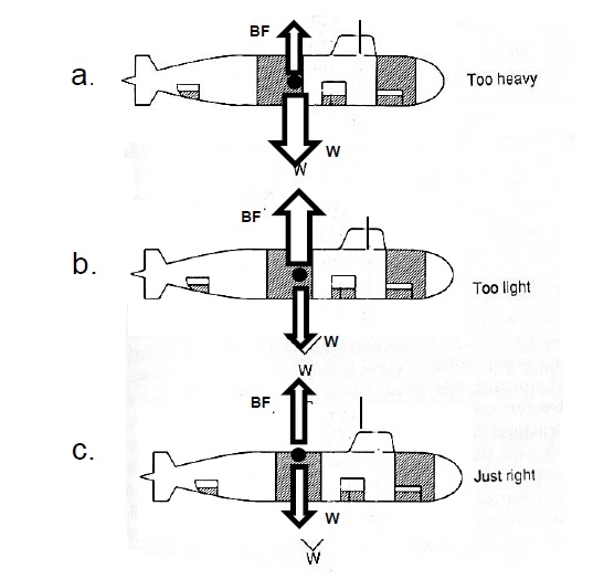
Fig. 2. Basic Sequence of Events Submarine Diving Cycles
Note: BF = Volume of Submarine x density of seawater
Weight = weight of submarines + ballast and stores
Figure 2a – A submarine ready to dive underwater must increase the weight of seawater and fill up the ballast tank to overcome the force of buoyancy of the pressure hull. In this case, where the buoyant force (BF) is smaller and the weight of submarine plus the weight of water (W) at the ballast tank is greater, the submarine will dive underwater.
Figure 2b – A submarine ready to surface at sea must increase the buoyant force (BF) by blowing high-pressure air to displace seawater out of the ballast tank. The buoyant force of the pressure hull and the empty ballast tank will increase buoyant force (BF) and overcome the weight of the submarine (W).
Figure C – A submarine ready to maintain neutral buoyancy to navigate between the surface of the sea and the bottom of the sea, the force of buoyancy (BF) and the weight of water in the submarine ballast tank (W) are equal in magnitude.
BALLAST TANK ARRANGEMENT
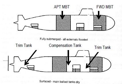
Fig. 3. General Arrangement of Ballast Tank of Diesel Electric Submarine
Main Ballast Tank (MBT)
The MBT is Located at the external section of the pressure hull, which free floods when the submarine is submerged. The purpose of the MBT is to allow major adjustments by the submarine to enable it to operate while submerged vertically, both upward and downward.
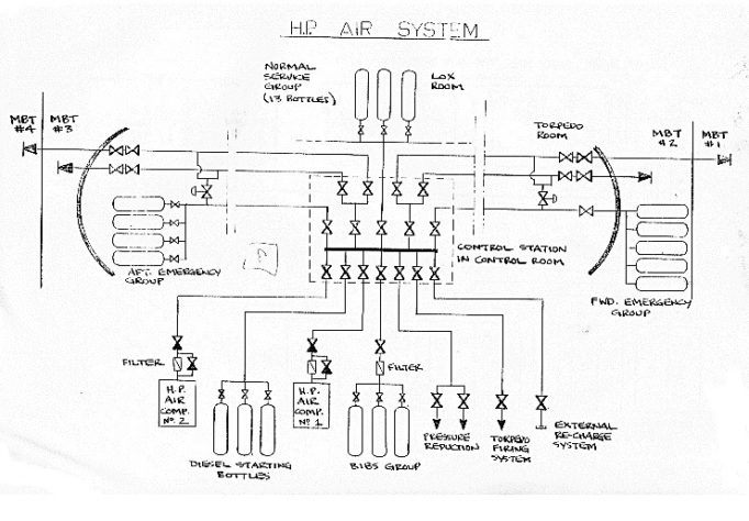
Fig. 4. High Pressure Air System for MBT
The high-pressure air system diagram is a very important component of the ballast tank that sustains the diving and surfacing of the submarine in all stages of operation.
TRIM AND COMPENSATION
When a positive and negative buoyant force (BF) is required, an action must be taken to maintain a condition of neutral buoyancy by adjusting the weight. This is achieved by the use of a compensating tank, which is located almost at the longitudinal center of gravity (LCG) of the submarine. The weight will cause a significant distance to the LCG to create a trimming moment (distance x weight), to trim aft on forward and the bow. A trim is the difference between the angle forward and angle aft of tilt with respect to the horizontal axis of the submarine.
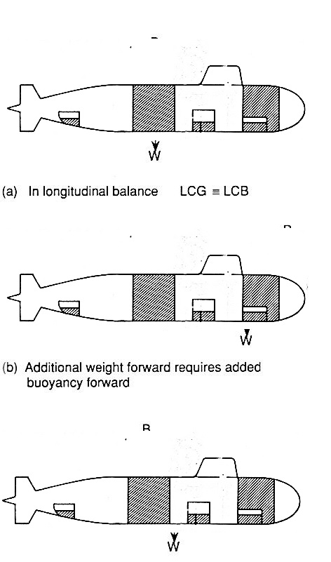
Fig. 5. Trim and Compensation Tank of a Submarine
A submarine operating below the surface of the sea compensates for variations in longitudinal moments (tons-meters) and weight by a compensation tank due to a change in density of seawater and distribution; and reduction due to fuel, water, stores, delivery of weapons systems, etc.
As shown in the trim polygon diagram in Fig. 6 as a graphical representation, the horizontal scale represents the variable ballast and moment about the trim axis of the submerged submarine, which is designated O (Aft moment and Forward moment).
The vertical scale represents the weight of the compensation tank. Each side of the polygon represents the weight and effect to the compensation tank. These tanks are identified in each side of the polygon.
The submarine trim and compensation polygon is a closed circuit that illustrates how a submarine will dive, surface and navigate underwater by adding or deducting the weight of water in the trim and compensation tank.
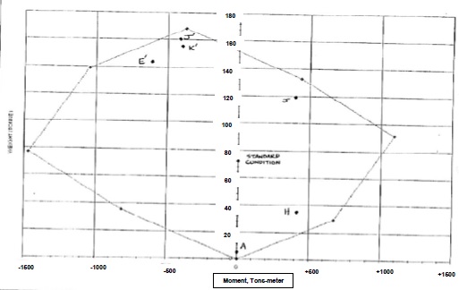
Fig. 6. Model of Trim Polygon Critical Data Points X-Y axis Comprising Coordinates in the Trim Polygon
Table 1. Example of Tim Polygon Data Sheet
The submarine will encounter some buoyancy problem if the weight of water slightly changes due to variations in density that could not be compensated. The buoyancy lines from the x-y coordinates are the limits of the trim and compensation tank effectiveness.
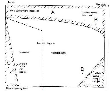
Fig. 7. Diving Safety Envelope
DIVING SAFETY ENVELOPE (Fig. 7) is an illustration of a submarine when operating under the surface of the sea.
- Critical parameter – this shows that when the submarine is operating at periscope or snorkel depth, it can encounter collision with deep draft surface ship.
- Submarine hydroplane pitch angle stabilizer or uneven ballasting of trim tank exceeds aft, with bow starting to dive deeper, loosing control and doing a crash dive.
- Submarine is unable to recover excessive flooding inside the pressure hull where the weight of water flooding the compartment is greater than the volume of the ballast tank.
- Submarine is gradually descending with the angle of hydroplane not greater than 30o and gaining depth with effective submarine propulsion motion control.
- Submarine is unable to recover and is totally lost at the bottom of the sea.
- Submarine is operating parallel to the surface of the sea at maximum pressure depth approaching the hull-collapsed depth.
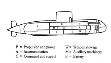
Fig. 8. Cross-Section of Double Hull Submarine
Legend:
P–Propulsion system, generators, control, switchboard, etc.
A–Accommodation, Crew billeting, habitability and life support system, etc.
C–Command, Control, bridge, conning tower, etc.
W–Weapon Stowage, torpedo tubes, torpedoes, etc.
M–Auxiliary Machineries, high and low pressure air, etc.
B–Battery, storage, charging system, etc.
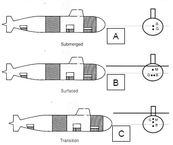
Fig. 9. Relationship of Center of Gravity, Center of Buoyancy and Metacenter of the Submarine Diving Operation
Fig. 9-a; the center of gravity (CG) is above the center of buoyancy (CB); the submarine will cause to submerge in upright position and navigate freely underwater.
Fig. 9-b: the metacenter of the submarine is above the center of gravity (CG) and coincides with the center of buoyancy; the submarine is floating at the surface of the water. Only 10% of the reserve buoyancy of the hull is above the surface of the water.
Fig. 9-c: when the metacenter and the center of gravity (CG) coincide with each other above the center of buoyancy, the submarine will cause to dive underwater.
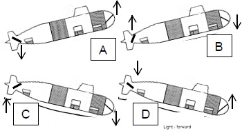
Fig. 10. Motion Sequence of A Submarine Under Motive Power of Propulsion System. Submarine under speed and power underwater is controlled by pitch angle of the forward and aft hydroplane in the following underwater cruising and vertical maneuvering situations of the hydroplane’s pitch angle (up and down) depth controlled setting.
Fig 10-a: Submarine is heading to the surface of the sea, the hydroplane pitch angle is forward up and hydroplane pitch angle is aft down.
Fig. 10-b: Submarine is heading to the surface but changes direction from surfacing to diving direction, hydroplane of pitch angle is forward down and hydroplane pitch angle is aft up.
Fig. 10-c: Submarine is heading for deeper dive but changes direction to surface, hydroplane angle of pitch is forward up and hydroplane angle of pitch is aft down.
Fig. 10-d: Submarine is heading for deeper dive, hydroplane angle of pitch is forward down and hydroplane angle of pitch is aft up.
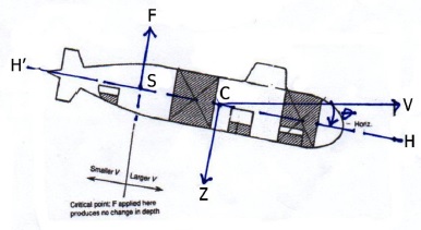
Fig. 11. Submarine Diving Trim Chinese Effect Phenomena
SUBMARINE DIVING TRIM CHINESE EFFECT
A phenomenon related to accurate measurement and concentration of weight inside the submarine – the CHINESE EFFECT – occurs when the effect of hydroplane control effectiveness at critical speed underwater of less than 2 knots, and the effectiveness of the aft hydroplane gliding underwater is progressively reduced.
The aft hydroplane’s vertical direction of control of force by pitch angle is in the opposite direction of the pitch angle of the forward hydroplane. That creates a moment of force, which tends to make it rotate at the neutral point or fulcrum at the center of buoyancy “C”. The forward hydroplane is near to the neutral point, and the effectiveness in the control of force at pitch angle causes heave velocity “V” with respect to the center of buoyancy “C” that creates the angle O from the horizontal axis of the submarine “H”.
“Z” is the direction of the center of gravity from point “C”. Heave velocity “V” forward is larger; opposite aft is smaller, and presumed to intersect from the horizontal axis of the submarine “H” to “S” where “F” tends to maintain depth from the surface of the sea, while the submarine is maintaining the momentum speed of advance.
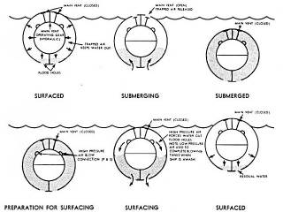
Fig. 12. Sequence of Events in Submarine Diving and Surfacing Operation
SEQUENCE OF EVENTS IN SUBMARINE DIVING AND SURFACING OPERATIONS
Submarine at the surface of the sea: air vents are closed to keep high-pressure air trapped inside the ballast tank; submarine maintains positive buoyancy (ballast tank and pressure hull)
Submarine submerging: air vents are open to release high-pressure air from the ballast tank; submarine gradually or quickly loses buoyancy due to flooding in the ballast tank (remaining positive buoyancy is inside the pressure hull)
Submarine submerged: air is replaced by seawater inside the ballast tank. Buoyancy is replaced by the weight of water in ballast tank (remaining buoyancy inside the pressure hull) is equivalent to the weight of water in the ballast tank; submarine is in neutral condition.
Submarine preparing to surface: air vents are closed, high pressure is blown inside the ballast tank to displace the water, gaining positive buoyancy.
Submarine surfacing: air vents are closed and high-pressure is increasing inside the ballast tank, and gradually or quickly releasing water inside ballast tank, thus, gaining positive buoyancy to the surface of the water.
Submarine at the surface: air vents are closed, high-pressure air is sealed and trapped inside the ballast tank with low pressure air maintaining the pressure to keep submarine’s positive buoyancy to 10% reserve of buoyancy (difference between the weight of the water inside the ballast tank and the total buoyancy of the submarine (ballast tank and pressure hull).
SUBMARINE SNORKELING AT PERISCOPE DEPTH WHEN CHARGING BATTERIES.
Submarine snorkeling takes place when the generators are in operation to charge the series of batteries that takes an estimated 5-8 hours to fully charge the battery banks. The submarine can operate underwater using batteries, depending on the load/speed, and battery-draining period of approximately 6-10 days. The battery charging time versus duration before batteries are drained of energy is called Indiscretion Ratio, normally equivalent to 10%.
At snorkeling depth, the submarine can launch buoy to connect to the atmosphere with fresh air and supply to the internal combustion engine (ICE) to complete the ignition-combustion cycle of the generators for operation, by charging batteries or by using AIP Engine.
The submarine, when operating at battery mode, can remain ultra-quiet and emit minimal acoustic signatures.
Note: The vent holes (Kingston valves) at the bottom of the MBT are always left open to keep seawater in and out. In order to gain negative and positive buoyancy, the water needs to escape from MBT by controlling low and high-pressure air.
Source reference:
- Business Insider, Russia launched a powerful new submarine named after ‘Vladimir the Great’ — and it’s just getting started by Ben Brimelow No. 27, 2017
- Wikipedia. List of Submarine Incidents since 2000.
- https://defencyclopedia.com/2016/07/06/explained-how-air-independent-propulsion-aip-works/
- https://en.wikipedia.org/wiki/Submarine_depth_ratings
- Egypt Business Directory, Submarine Battery Industry Report to 2022 By Manufacturers, Region And Application by Paul Kaif.
- https://www.marineinsight.com/naval-architecture/submarine-design-structure-of-a-submarine/
- https://defencyclopedia.com/2016/07/06/explained-how-air-independent-propulsion-aip-works/
- Ref:https://forum.sub-driver.com/forum/general-topics/1407-russian-submarine-id/page9
- Ref:http://gentleseas.blogspot.com/2014/07/air-independent-propulsion-game-changer.html
- http://www.sivakrishna.com/stfaq.html
- http://fashion.stellaconstance.co/fuel-works/
- https://fas.org/man/dod-101/sys/ship/eng/reactor.html
- https://www.sundayguardianlive.com/opinion/12210-indian-navy-has-submarine-problem
- Modern Ship Design by Thomas Gilmer.
- Brassey Ships and Submarine.
- Submarine Design Concept, University College London Department of Naval Architecture.
About the Researcher:
CAPT TOMAS D BAINO PN (Ret) completed his post-graduate studies in Submarine Design at the Department of Naval Architecture, University College of London, United Kingdom of Great Britain, as a recipient of the UK Ministry of Defense sponsorship grant. Capt Baino is an associate editor of the Maritime Review, providing a series of articles on Naval Ship Design and presently serving as Naval Architect Consultant with the Department of Transportation and Philippine Coast Guard Project Management Office on ship acquisition program.